|
You have probably seen SSB signals that are 8 KHz or wider. Chances are very good that these are the current crop of Yaesu transceivers. You don't have to be that guy. Here's how.
I stipulate to being a confessed Yaesu fan. The FTDX101 replaces my previous FT-950. These radios brought me DXCC mixed Phone/CW, DXCC digital, and Triple Play WAS, using only dipole antennas hung in trees. You can't work them if you can't hear them. Latest Sherwood receiver tests demonstrated that down conversion with a real crystal roofing filter offered superior receive performance. I even ordered the 1.2 KHz SSB filter, and found it very useful, despite my initial skepticism.
https://en.wikipedia.org/wiki/Roofing_filter
This is a long technical article. If you just want the settings, use the menu at the right to go directly to the settings which I found effective. The purpose of this article is not to discourage you from buying a Yaesu product; instead it is to mitigate the problems associated with misadjustment of controls having a negative impact on transmit distortion products. It would have not been necessary if Yaesu had provided clear instructions regarding adjustment of the unique AMC feature.
This page is only about transmit audio.
If you want to improve receive audio, see how to replace the stock speaker or build your own external speaker for much less than the accessory SP101 or replace the speaker in the SPS101 power supply/speaker for the 200 watt version, see this article for more information.
I enjoyed my FT-950 on SSB and AM, and expected the same with the FTDX101. I spent a whole day in the HRO store in Manchester, NH evaluating the top of the line rigs, telling them that I was going to purchase a radio that very day. Support your brick and mortar ham radio equipment retailer. Don't buy a radio without test driving it first. As useful as QST reviews or Sherwood reports are, you need to try the features and ergonomics before spending thousands of dollars.
I would like to hear from owners of the FTDX10 who try the settings recommended on this page. If you find any discrepancies, please contact me and I will make corrections or remove references to that radio. The FTDX10 is reputed to be the same design as the FTDX101D, except that the VC tune and the second receiver is deleted. The FT710 is a fresh pure SDR design, and my conclusions may not apply to that radio.
While the comments on this page are my personal opinion, they are based on solid reputable sources such as the Yaesu manuals, the ZL3DW book, the W8JI website, the Sherwood tests, the QST FTDX101 reviews, and the comments of knowledgable FTDX101 owners such as K4TK. In each case, I provide links and quotes for you to investigate these matters yourself.
Yaesu currently has three transceivers which employ the unique feature of AMC: the FT710, the FTDX101D and the FTDX10. No other manufacturer employs this. It does look like this will be the standard for new Yaesu rigs, so we need to better understand how they work to get the best performance. This feature is shrouded in mystery, not helped by the sparse information in the Yaesu instruction manual. I recommend you immediately pick up a copy of the ZL3DW book "The Radio Today guide to the Yaesu FTDX101D" for an explanation of many topics not explained in the manual. If you like the free stuff you are reading here, you are going to love the book; order it now. The FTDX101D and FTDX10 have some of the finest receivers available as of 2023. The new FT710 is no slouch either, for a lower cost transceiver. It is bound to give the ICOM IC-7300 some competition. It IS possible to design a pure SDR and still get good receiver overload performance. The FLEX 6700 (but read footnote y, maybe not so good) and Icom R8600 also get scores in the top 6 of the Sherwood receiver test list. The Elecraft K3S (a down conversion architecture) is in that grouping. I am hopeful the Elecraft K4 with the down conversion hardware accessory will meet these difficult standards. But this article is not about the receive performance of the FTDX101D, its about a transmit issue, and how to properly adjust the obscure AMC function unique to this radio. Anyway the paper manual for the Yaesu FTDX101 doesn't explain much about AMC. There was a later software update which turned the AMC on all the time, and had some instructions. Its better than the manual. Give it a read and see if it helps you. https://www.yaesu.com/downloadFile.cfm?FileID=15133&FileCatID=42&FileName=Important%20Changes.pdf&FileContentType=application%2Fpdf
I remember when you got a good microphone and adjusted the mike gain so the ALC kicked up in the highlighted region on the meter, and you got good sounding punchy audio without a lot of complications. If you want a new Yaesu transceiver, those days are gone forever. For SSB, you MUST learn how to set the AMC function to avoid splatter. For AM, you MUST disable the AMC function as best you can, or you may get either splatter or weak under modulation. If you insist on operating digital modes with an interface that connects via the mike input, you are making a lot of unnecessary work for yourself, and will likely wind up with a dirty signal. When misadjusted, these Yaesu radios have come to have a reputation of wide splattering signals. This is not a beginner's radio, and there is a steep learning curve to get a clean signal, with scarce practical information in the Yaesu manual.
The problem of slow attack time or overshoot from marginal ALC circuit designs seems to be universal throughout all amateur transceiver manufacturers. Likewise, third order transmit distortion products struggling to make -30 dB appears also to be universal with 13.8 VDC final amplifiers. These problems are compounded by modern solid state amplifiers, even when powered from 50 volt supplies. The purpose of this web page is to obtain the best possible performance from the FTDX101 and manage the unorthodox AMC feature.
The ZL3DW book makes the following statements:
"TIP: The Yaesu operating manual says that the AMC should be adjusted so that the COMP meter never deflects past 10 dB. This seems to be impossible and is causing all sorts of confusion on the forums. My advice is to ignore the statement in the manual and make an adjustment that swings over most of the meter scale rather than sitting mostly in the region between 15 dB and full scale. A setting of 75 to 80 seems appropriate." Page 10
"The good news is that I did not see any evidence of envelope distortion at any AMC setting. I doubt that Yaesu would allow the transceiver to be set at a level that causes RF splatter! Surely that would be irresponsible." Page 16
The QST November 2019 review of the FTDX101D states:
"Bottom Line: The Yaesu FTDX101D is a very effective, full-featured, high-performance transceiver that would work well in most stations, especially those involved in serious contesting or DX chasing, where strong close-in signals abound. Its very low transmitted phase noise, narrow keying sidebands, and good IMD characteristics will be appreciated by other operators using nearby frequencies."
"Transmit quality is equally impressive, making the FTDX101D a good neighbor
for others using nearby frequencies. For example, the FTDX101D greatly
exceeds FCC requirements for harmonic and spurious suppression. It also
has excellent transmit phase noise, keeping broadband noise low for other
receivers tuned to the same amateur band.... On SSB, the transmit
intermodulation distortion (IMD) is relatively low, especially the higher-order
products that can interfere with stations on nearby frequencies."
Hundreds of FTDX101D users, myself and those who have criticized my splatter on air included, have determined those statements to be demonstrably incorrect. How the QST reviewer came to those conclusions is baffling, and why they did not identify this problem and suggest solutions is disturbing.
Based on currently available information, it seems that at a minimum, Yaesu needs to immediately issue a white paper instructing users exactly how to perform adjustments to mike gain, AMC, and processing to achieve minimum distortion products on all voice modes. Further, it may need to suspend any designers involved with the FTDX101, FTDX10, and FT710 transmitter portion, and commission a fresh design team composed of seasoned RF designers with direct experience in HF voice and digital sound card modes to do an independent evaluation of the current designs. They may need to have authority to immediately suspend production and issue a hardware recall. They also should possibly have authority to immediately begin redesign for a FTDX101E and a FTDX101E/MP successor.
|
Like it or not, Software Defined Radios (SDR) are here to stay. The human interface is not what it used to be when my primary radios were a Heathkit SB-102 and a Ten Tec Corsair. The Collins 32S1 set the gold standard for -40 to -50 dB distortion products, when the mike gain was properly adjusted. Today's transceivers struggle to make -25 or better. Sherwood tests posted by DJ0IP bear this out for the FTDX101D. My tests corroborate these results. I used the K1VL remote SDR with the pop up spectrum display.
http://sdr.k1vl.com:8073/
I also used my own Siglent SSA 3021X spectrum analyzer and a -40 dB sampling port.
. See
https://www.dj0ip.de/app/download/5814015747/Yaesu+FTdx-101D-G1+%28002%29.pdf
| FTDX101D Transmit odd-order IMD |
|---|
| Power 100 watts | odd-order product dBc | Add 6 dB for PEP method |
|---|
| Band | 3rd | 5th | 7th | 9th |
| 6m | -25 | -29 | -37 | -48 |
| 20m | -33 | -32 | -41 | -53 |
| 80m | -37 | -38 | -41 | -44 |
| Power 50 watts | odd-order product dBc | Add 6 dB for PEP method |
|---|
| Band | 3rd | 5th | 7th | 9th |
| 6m | -26 | -37 | -51 | -61 |
| 20m | -26 | -35 | -49 | -55 |
| 80m | -34 | -35 | -40 | -48 |
Note that the distortion gets worse at lower power levels (50 watts). Likely at the 30 watts I use to drive my KPA1500, the 3rd order distortion is -23 dB or worse on 20 meters! These steady state two tone tests are not fully representative of an actual speech signal, which stops and starts, causing the slow attack time of the ALC and AMC circuits to further degrade the signal. W8JI proposes a three tone test method which may be more informative of the dynamic state of an actual voice signal. At the end of this article is a discussion and link for that technique. These figures are representative of ALL currently manufactured radios and solid state amplifiers. As I stated earlier, this article is not a hit job on Yaesu.
QST also did reviews of both the 100 watt FTDX101D and the 200 watt FTdx101MP. The results are similar to those done by Sherwood.
FTDX101D:https://static.dxengineering.com/global/images/technicalarticles/ysu-ftdx-101d_hc.pdf
FTDX101MP:https://www.yaesu.com/downloadFile.cfm?FileID=16627&FileCatID=156&FileName=FTDX101MP%20Product%20Review%20%28December%202020%20QST%20%2D%20ARRL%29.pdf&FileContentType=application%2Fpdf
The results for the 100 watt D version: -35 dB third order worst case 80 meters at 100 watts; -26 dB on 20 meters at 50 watts
The results for the 200 watt MP version: -27 dB third order worst case 17 meters; -29 dB worst case 20 meters; at 50 watts.
These figures are adjusted by 6 dB to agree with the Sherwood method, which correlates well.
Measurements from one radio to the next are highly dependent on how well the final transistors are matched, as well as how the bias is set and how well balanced the bias is between the two transistors. In general, a FET amplifier with a 50 volt supply should be significantly better than one which is running on a 13.8 volt supply.
Part of the problem today is many have a spectrum scope on their radio, or have access via the web to a spectral display. The lower threshold level on these web SDRs is often not adjustable, so it is not calibrated to a real world signal level, especially on a "waterfall" display. Some of the better Kiwi SDRs like the K1VL have an adjustable spectrum display. So everyone gets upset when they see "whiskers" on the sides of a signal, be it theirs or someone else's. This sort of display was not commonly available only 5 years ago. Besides the obvious lowering of performance standards from vacuum tube equipment to solid state transceivers and amplifiers, there is an increased awareness of signal purity. The real bottom line is, with a good receiver with the noise blanker turned off and set to a narrow CW bandwidth, does the signal seem wide when tuning off to the side? If you cannot hear it, it does not matter what some arbitrary uncalibrated display says. We need to focus on a real world problem. The ARRL Clean Signal Initiative is just such a step.
How does the FTDX101 compare to older Yaesu radios? "The ALC of the FTdx-3000 operates like all the Yaesu rigs I have used recently, including the FTdx-5000D, the FT-950 and this new FTdx-3000. The time constant is very fast, and Yaesu has purposely made this design choice to enhance its speech processing. Personally I think processing should all be done either in the IF (RF compression or RF clipping) or in DSP, but not with the ALC. In the case of the 5000D, the fantastically clean signal one can put on the air when the exciter is in class A is degraded significantly when ALC is used even to a modest amount." It should be noted that contest grade radios no longer offer the option of Class A operation, which provides exceptional transmit distortion performance. This would go a long way to reducing exciter distortion when employing a linear amplifier.
https://www.dj0ip.de/sherwood-forest/sherwood-hf-xcvr-tests/icom-ic-7851/
For comparison, what do the Sherwood tests reveal about the flagship ICOM IC-7851 transmit distortion products? Again, only -26 to -28 dB down for third order products. This radio is selling for $13,300 and buy it now if you can, because its discontined. Much more expensive than the Yaesu FTDX101 and not nearly the performance. If you compare feature for feature, this is the radio that Yaesu wanted to compete with, right down to the 1.2 KHz SSB filter.
https://www.dj0ip.de/app/download/5806181607/IC-7851+transmit+IMD+by+band.pdf
On 20 meters at full power, an astonishing -22 dB third order products, in tests done by Rob Sherwood!
https://www.dj0ip.de/app/download/5806181603/IC-7851+Transmit+IMD-A.pdf
This problem is exacerbated by modern solid state amplifiers, which also struggle to make -30 dB down distortion products. A well designed tube amplifier will often go to -40 dB down or better distortion products. When added to the source distortion of the transceiver, no wonder people see so many "whiskers" in the spectral and waterfall displays on modern radios. This conundrum is the reason the ARRL has its "clean signal initiative."
https://www.arrl.org/files/file/QST/This%20Month%20in%20QST/2023/06%20june%2023/0623%20article%20Ritz.pdf
The next generation of radios will be built around the principle of adaptive pre distortion. My Elecraft KPA1500 amplifier has a port already installed for this purpose. However, only ANAN and maybe some of the more exotic SDRs have the capability to employ this technique at this time. Elecraft may include it in newer versions of the K4 at a later date. Unfortunately, these radios do not deliver the receive performance I demanded. The FTDX101 does not have the adaptive pre distortion feature, or a Class A final option.
Contest University had the following eye opening statements:
A typical SSB signal today from a 13.8 volt PA is over 10 kHz wide at -60 dB.
QST review Elecraft KPA1500 amp listed third-order IMD at -30 dB PEP
https://www.contestuniversity.com/wp-content/uploads/2020/05/NC0B-Contest-DX-Performance-a-Complex-Subject-Today-Great-RX-Performance-TX-Limitations.pdf
Misadjustment of the transmit audio has, perhaps unfairly, given the FTDX101 a reputation for excessive splatter. In the process of integrating a new legal limit KPA1500 amplifier into my shack I became much more visible and collected a number of complaints from neighboring operators on the band.
I simply had to do something about it before a formal complaint from the ARRL monitors. There is a lot of information on the internet, a lot of it anecdotal and simply wrong. Read some background, including the author of the book at:
https://groups.io/g/FTDX101D/topic/question_about_amc/84122213?p=Created,,,20,2,20,0::recentpostdate/sticky,,,20,2,240,84122213&next=1
Given the problems I have identified here, I would suggest caution when operating near band edges on SSB. For instance, operation on 3.999 MHz LSB might result in out of band distortion products in the area where you would expect to find a USB signal from your transmitter. This will unlikely meet a -43 dB spec for out of band emissions, especially if you are using an LDMOS amplifier. A more careful frequency setting of 3.995 or lower is advised. I never use my FTDX101D on 60 meters, due to the more demanding requirements to remain within a narrow "channel." I have never previously found it necessary to take such precautions. Until someone (please, Yaesu?) publishes "Proof of Performance" data, along with the menu settings used to accomplish the goals, I will take the most cautious approach. A firmare update or another hardware recall addressing the problem may be necessary if the 60 meter Proof of Performance cannot be achieved.
97.307 (a) No amateur station transmission shall occupy more bandwidth than necessary for the information rate and emission type being transmitted, in accordance with good amateur practice.
(d) For transmitters installed after January 1, 2003, the mean power of any spurious emission from a station transmitter or external RF power amplifier transmitting on a frequency below 30 MHz must be at least 43 dB below the mean power of the fundamental emission. |
|---|
OK, don't take my word for it. The steady state tests show that the FTDX101 does not achieve -30 dBc IMD on steady state tones. The Sherwood tests shown below demonstrate that with transient state signals like voice, the ALC and AMC lose control and result in splatter not anticipated from extrapolation of the steady state data.
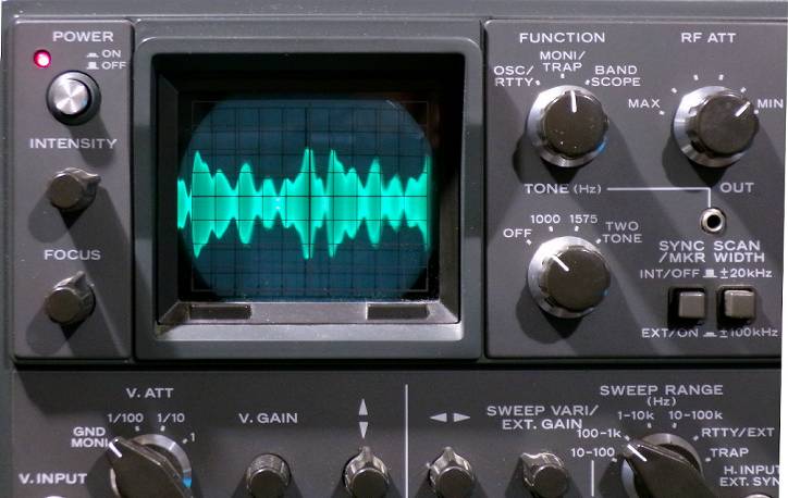
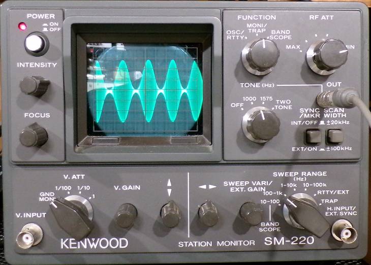
The scope photo below is a better representation than would be provided by a conventional non storage monitor scope such as the Kenwood SM-220. Note the excursions outside the set power level of 30 watts. If this signal is fed into an amplifier which achieves full rated output with 30 watts drive, that amplifier will generate splatter. If the FTDX101D is set to 100 watts and operated without an amplifier, the FTDX101D output stage will be overdriven into saturation, resulting in splatter in excess of that predicted by steady state IMD tests using a two tone source.
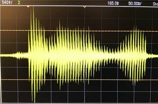 |
SSB overshoot set for 30 watts output.
Horizontal cursor lines are set at 30 watts |
|
Output power overshoot occurs on CW, and even more so on SSB. When output power is set for 30 watts, typical of a low drive linear amplifier, peak power can exceed 120 watts, four times the desired power setting. When set for 30 watts output, a peak reading wattmeter has captured peaks in excess of 190 watts. There have been some email reflector reports of the FTdx-101D causing linear amplifiers to fault on SSB due to the excessive overshoot. |
https://www.dj0ip.de/app/download/5814015747/Yaesu+FTdx-101D-G1+%28002%29.pdf
(Sherwood tests)
The unescapable conclusion is that the ALC and AMC circuits in the FTDX101D are incapable of ensuring a clean signal in SSB. I attempt here to find AMC settings which come as close as possible to "good amateur practice" to mitigate this problem. AMC settings above 55 will positively guarantee that your FTDX101D will generate unacceptable splatter. All manufacturers need to reevaluate their design process in regard to ALC function to avoid this transient state control failure.
Speaking as a designer, I know there are simple digital techniques, such as a digital delay line, which could be inserted in the audio section to solve this problem. It isn't that expensive. Its called a "look ahead" processor. The actual audio signal is delayed by a small amount (enough for the ALC or leveling circuit to reapond to a transient), and the control voltage arrives AHEAD of the transient peak in the transmit audio. This would allow any manufacturer to build a transmitter with low IMD products from transient state inputs. It would not depend on any DSP chip features to achieve this goal. In the future, the DSP technology should include such a "look ahead" processor inside the DSP engine, but for now, this ia a patch that would solve the problem. This could also augment the "predistortion" features currently included in only high end DSP only radios like FLEX and ANAN.
For the ARRL review to have completely ignored AMC adjustment in their article is inexcusable. Also, new testing criteria need to be invoked to alert buyers to this issue, even if it means stepping on the toes of an important advertiser. Otherwise, a "Clean Signal Initiative" will be utterly toothless.
For Yaesu not to have issued a bulletin after all this time alerting owners to this issue, and showing them how to mitigate it, is also inexcusable.
I would hope that you would want a understanding of how the radio works when you spent so much money on it. It would help you get more out of the rig and allow you to customize it to your voice. This radio is a complex competition grade radio that you should learn more about than the default settings. I loved the technical aspects of amateur radio, and it launced a great career in electronics. Some people memorized the answers to the license test. That said, click here to skip to the settings tables at the end and have a nice day.
This is not a slam job on Yaesu. In fact ALL the big three manufacturers have had the exact same problems over the years. You would think that after one episode of slow ALC attack time, with the resulting power overshoot, manufacturers would set design criteria that eliminate the problem at the beginning. This often requires a hardware fix that causes expensive rework, with return shipping from irritated users of first production run radios. Do they consider them Beta testers who work out the design flaws without any pay? How about the power amplifiers that are damaged by excessive RF spikes on leading edges of CW or SSB waveforms, whose problem is that? Do they hire a team of green software oriented people who have no prior RF experience each time they bring out a new radio? Don't they realize the transmit audio section is not a PA system but results in an RF signal? I guess its the new work ethic where a product can be shipped before its fully tested, and software patches are issued to clean up the mess after the fact. Regardless, I am a hardcore Yaesu fan.
The Yaesu FTDX101D was the subject of a recall of early production units for a hardware fix which allegedly partially corrected a slow attack time of the ALC circuit. Page 179 of the ZL3DW book lists the serial numbers of FTDX101 which need to be sent back to the factory for hardware changes to correct this problem. Subsequent production is supposedly corrected. There are apparently lingering problems associated with the AMC circuit. This is one of the reasons I delayed purchase of this radio. I previously owned a late production FT-950 and was very satisified with it. There was a hardware fix, and then a later PEP or Performance Enhancement Progam. I also own a late production FT-450D, and its an excellent basic radio that succeeded the earlier FT-450. However, the 450D, after multiple hardware revisions, still has large overhoot. I saw what happened with the FT-991, which eventually resulted in the otherwise great FT-991A.
A new problem has been created by the use of SDR techniques to perform functions that were normally done by analog components like resistors, capacitors, and op amps. These are intuitively understood and react to signals in a linear fashion. Digital methods introduce very different sounding distortion products and produce strange sounding grunge. When an SDR ALC circuit overloads, it doesn't just clip, it adds digital artifacts to the signal. Compounding the problem, while in receive the FTDX101 has a sharp crystal filter to limit the bandwidth, in the transmit chain the crystal filter is NOT in the signal path to clean up the splatter, as would have been the case in a classic SSB radio from not too long ago. The ICOM flagship IC-7851 is no different, as shown from the comparison above. On the other hand, Flex and other pure SDRs often transmit very clean signals. This proves it CAN be done, with careful design.
I have no explanation for where the "AMC" came from, why it was deemed necessary (when the redundant ALC or compression was available) or even what the acronym stands for. It was part of the original design. A later software patch made it impossible to turn off. I speculate this was to compensate for the slow ALC attack time. That would have worked if the ALC attack time was fast enough, like older Yaesu radios. The menu settings for AMC time constant are for the DECAY time after the audio spike has happened. You can minimize AMC by setting it to 100. But my experiment shown later proves you cannot totally defeat it. Also, a setting of 100 or anything above 55 will increase splatter.
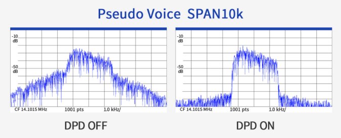
UPDATE 1/31/2024: Icom has just announced a software update for its IC-7610. This update adds Digital Pre-Distortion (DPD) similar to the methods used in the ANAN SDRs to reduce IMD.
https://www.icomjapan.com/lineup/products/IC-7610/
Check out this stunning improvement in transmit band width from Icom's write up. Wouldn't it be great to get this kind of software support from Yaesu?
Nowadays, you get a hand mike that nobody uses after initial tests, it gets thrown back in the packing box for when you sell the radio when you are done with it. I remember when you got a good microphone and adjusted the mike gain so the ALC kicked up in the highlighted region on the meter, and you got good sounding punchy audio. Those days are gone forever. The FTDX101D hand mike is an electret condenser mike, which is very flat in response rather than having a "presence rise". Some Yaesu hand mikes have a switch on the back labelled 1 and 2, which allows you to select between muffled and even more muffled. This seems to grow out of a difference in spoken Japanese and spoken English (which needs more boost in the highs to be understood). You will have to make that up in the EQ settings. Hand mikes also have the noise caused by you holding in the PTT button. Most people move on quickly. If you need a scan button, that's a consideration.
The Heil mikes are popular and pricey. Heil sells a very good cable which is absolutely essential because the mike input on some Yaesu radios may be a BALANCED input. I used a mike cable I had bought for my previous FT-950, which definitely had a balanced input. It will work on either balanced or unbalanced input Yaesu radios. I checked further by ohm tests and the service manual to verify that the Yaesu FTDX101 turns out to be UNBALANCED. In other words, one side of the mike element is connected directly to ground. The other mike element is connected to the radio's transmit audio chain input. If it were balanced, you must not ground one side of the two wire balanced input or you will get distortion and RF in the audio system. Be certain you order the correct mike cable to match the FTDX101D, and be sure it has the correct number of pins on the microphone end. You need 4 pins for a Heil hand held mike with a Push to Talk button. You will need 3 pins on the mike end for a standard vocal mike with no PTT button. I prefer a mike on a boom, to declutter my desk for logging, keyboards, CW key, etc. The mike should have a rising characteristic like the classic D-104, 1933 technology that beats many modern products. The Heil #4 element is very restrictive and few lows for DX work, but for casual ragchews you will get complaints. The #5 element is muffled for my taste, and some Heil mikes are filled with styrofoam inside the head, which adds to that. If you don't believe me, depending on the Heil model, unscrew the cover on the head and look. I have not tried removing the styrofoam to see if it improves matters, and it could damage the mike if you do that. Heil makes a mike with #4 and #5 elements and a switch to select them, which was popular witih contesters.
I like the Heil mike boom and a Behringer XM-8500, which does have a rising characteristic for presence and articulation which improves intelligibility. It does this without cutting lows, which can easily be controlled with the EQ. It sells for an amazing $25 if you shop around, and I get "broadcast quality" reports with it at the 50-3050 transmit bandwidth. Of course you have to provide a mike cable, as you would with any microphone, even a HEIL. I do not use TTBF for reasons explained later. I have even used the XM-8500 on my AM rigs.
See AD5GG on XM-8500: https://www.ad5gg.com/2017/10/12/behringer-xm8500-for-ham-radio/
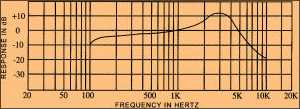
Behringer XM-8500 mike compared to Astatic D-104 mike; rise about 10 dB at 4 KHz
I now use an MXL BCD-1 mike and a MAX audio processor with a K7DYY full legal limit class D solid state transmitter for AM. It costs about $150. The pop screen from BSW for the Electrovoice RE320 fits if you install a longer screw. This sort of mike is overkill for an SSB radio, but is a great mike with a good look, and very reasonably priced for the frugal ham. In the shack photo, it will look like you spent the big bucks on an Electrovoice.
UPDATE 1/26/24: The Behringer XM-8500 mike with my voice showed a sort of sawtooth peaky waveform. This was handled well by all my other rigs. However, the 14 bit DSP and circuitry in the FTDX101D did not seem to tolerate it, and because of the slow ALC attack time, seemed to contribute to IMD and splatter. Your voice may not have this problem.
I replaced it with a HEIL HM-10 dual element mike with a #4 and #5 switchable element. It also incorporates an internal pop screen, which reduces susceptibility to "plosives." This resulted in a noticeably cleaner signal, believe it or not, as viewed on K1VL spectrum analyzer. The HM-10 has a presence rise peak for both elements. The #5 gets good reports in roundtables. The #4 element gets compliments when working DX for clarity and punch. The best of both worlds, and it solved my IMD problems with the FTDX101D. Give it a try. Some people are praising the HC-6 element used in the headset mikes, which has more low end than a #4 element. Research it and see if its for you.
https://heilhamradio.com/wp-content/uploads/2018/05/Heil-HM-10-XD-IB.pdf
NOTE: This HM-10 mike has a 4 pin connector on it and requires the matching cable:
https://heilhamradio.com/product/cc-1-y-adapter-cable/
I have also gotten good results with an older MD-100 Yaesu desk mike (which has been updated with new similar models). It has a lot of possible settings for frequency response, and the newer ones are even more versatile. I just prefer a boom mike and a foot switch for my operation.
There are three interacting controls for transmit audio: MIC gain, and AMC and COMP levels. Also, ALC is involved in the control of transmit power and distortion products. These interact in non intuitive ways, and can generate unacceptable amounts of distortion products much in excess of the commonly accepted standard of -30 dB from a whistle or CW waveform of the same power. Most new solid state amplifiers struggle to meet that standard, and a dirty exciter only adds to the QRM and complaints of splatter.
This situation is not helped by the lack of information in the Yaesu manuals. It would be helpful if a block diagram showing the signal path through these circuit elements was provided. Speculation says that the mike preamp and a low pass filter (to prevent aliasing) are the analog elements, and the path from there goes directly into the SDR digital engine. The EQ (concieved by Bob Heil), AMC, PROCessor, and ALC elements are all inside the SDR chip. Nothing is disclosed about the "secret sauce" inside that chip or its programming. Apparently a component value was changed in a factory recall to correct deficiencies in the ALC circuit in early production models. So it still may be possible to further improve the performance either in hardware or firmware. I intend to dig into the service manual and schematics to discover if the speculation about the signal path is valid, and will report my findings here when I am able.
In the menu OPERATION SETTINGS/TX AUDIO there are two settings for PROC LEVEL and AMC RELEASE TIME. The default settings are AMC and MID respectively. These also interact with the above noted front panel knobs, and may also result in splatter. Does the PROC LEVEL just affect the display on the FTDX101D screen, or does it prevent the adjustment of the actual processor, and impose some arbitrary default? It seems illogical to have a setting which disables the ability to adjust the PROC level. We will have to experiment and discover, because there is no clear explanation of this.
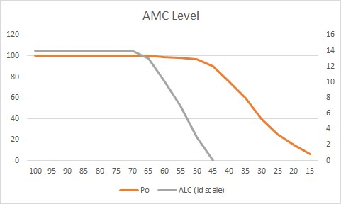 On page 16 of the ZL3DW book is a chart and discussion of the "AMC" feature of the audio chain. It really clarifies the effect of the AMC level control. If you like the free stuff you are reading here, you are going to love the book; order it right now. There are many features explained. There is also a section which tells you what menu item to fix if you have a certain symptom of misbehavior. On page 16 of the ZL3DW book is a chart and discussion of the "AMC" feature of the audio chain. It really clarifies the effect of the AMC level control. If you like the free stuff you are reading here, you are going to love the book; order it right now. There are many features explained. There is also a section which tells you what menu item to fix if you have a certain symptom of misbehavior.
In addition to this, we are confounded by the Parametric EQ settings. These are not intuitive. See the discussion later to understand how to adjust a Yaesu Parametric tranmit EQ. However, you will have to have some boost to the highs to get a proper picture of the distortion, which increases with the amount of energy at various frequencies. So pick a set of EQ settings or temporarily use mine in the table at the end of this article for a starting point.
On the left of the chart is power output; on the right is ALC indication as read on the calibrated final drain current Id scale. On the bottom are values of AMC level. The lesson here is that with a constant mike setting of about 25, the transmit power can be adusted by the AMC down to zero! At mike settings of 25, the ALC can be forced to well above the "normal" range to S9+30 dB or more. These extreme settings will surely result in splatter in ANY well designed transmitter.
What the ZL3DW AMC graphic makes clear is that AMC action begins at settings below 70 and effects become more pronounced as you go down to zero. The RF power output falls off as a roughly linear function as you adjust toward AMC=zero. The important ALC action (a relative indicator of potential distortion products) also falls off in a similar fashion. Various people have quoted Tim Factor, the Yaesu head tech, as recommending no higher than 55 for SSB. My observations of distortion indicate that keeping the ALC meter so that it does not move at all results in less distortion products and splatter. If you can sacrifice the power output, zero deflection of the ALC meter will be the best reduction in splatter that you can achieve. This is essential if you use an amplifier, because it adds its own distortion to the signal, but you can make up the power loss in the amplifier.
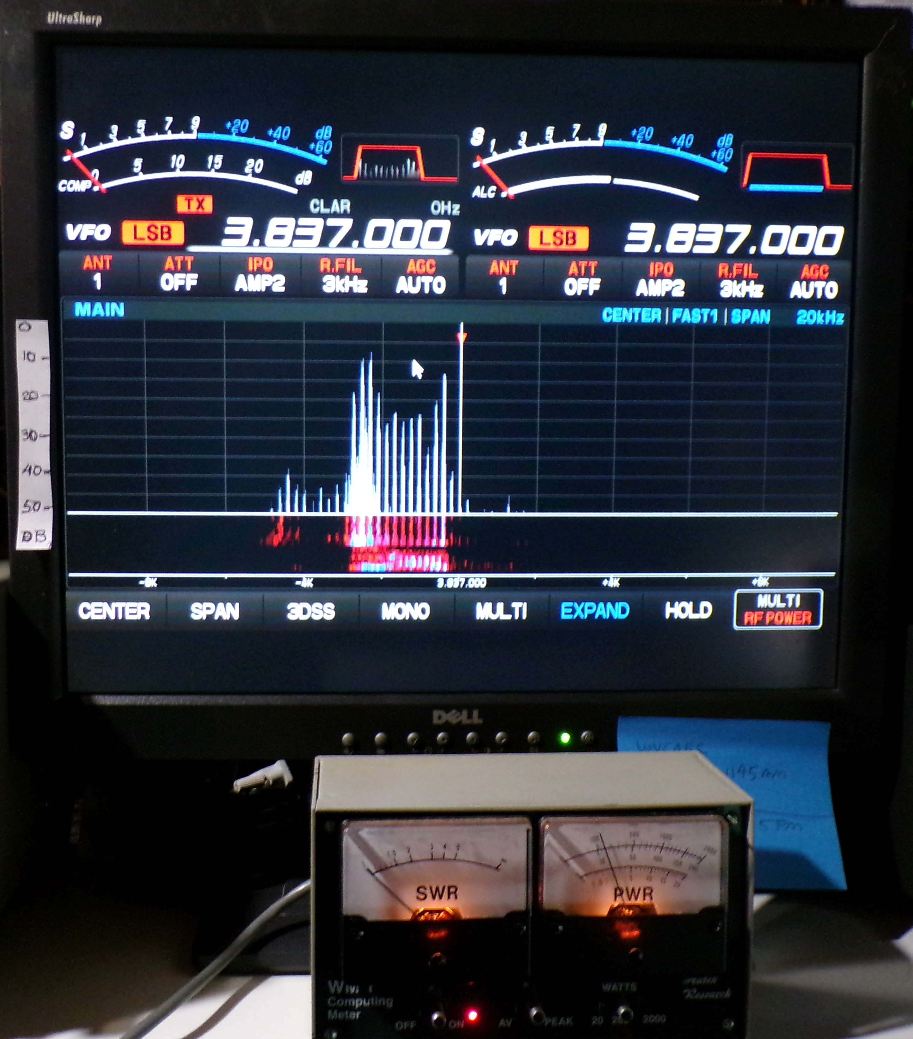
Fortunately, ZL3DW explains an undocumented feature in his book on page 187. The native spectrum scope will display the FTDX101D transmit output spectral purity. I used a 20 watt power setting for these tests, because it was about right to drive the linear amp to a reasonable level approaching its output, but not so high it was too much drive. Temporarily set the multifuncton knob to control LEVEL using the MENU. Transmit 20 watts CW and observe the spectrum display; adjust the LEVEL control so that the bright line representing the CW carrier just touches the upper line on the display. This works best with the S meter displays minimized and the spectrum display maximized, with as little waterfall as possible. Do not use MONO or you cannot see the ALC function because the right hand meter disappears. Consult the Yaesu manual which explains the display adjustments. Set the transmit band width to 50-3000. Set the transmitter for LSB on 80 meters. Set the SPAN for a 20 K wide display. That is ±10 KHz from the center carrier frequency. Any products to the right of the center frequency marker are in the UPPER side band and represent distortion products. Any products to the left of 3 KHz from the carrier are distortion products.
Each horizontal line in the grid represents 5 dB down from the peak main signal. Now switch to SSB and observe the spectral output. Any signal that is below the 6th line down is -30 dB from the main signal, considered passable performance on distortion products. That is your goal when adjusting all the various MIC gain, AMC, and PROCessing LEVELS.
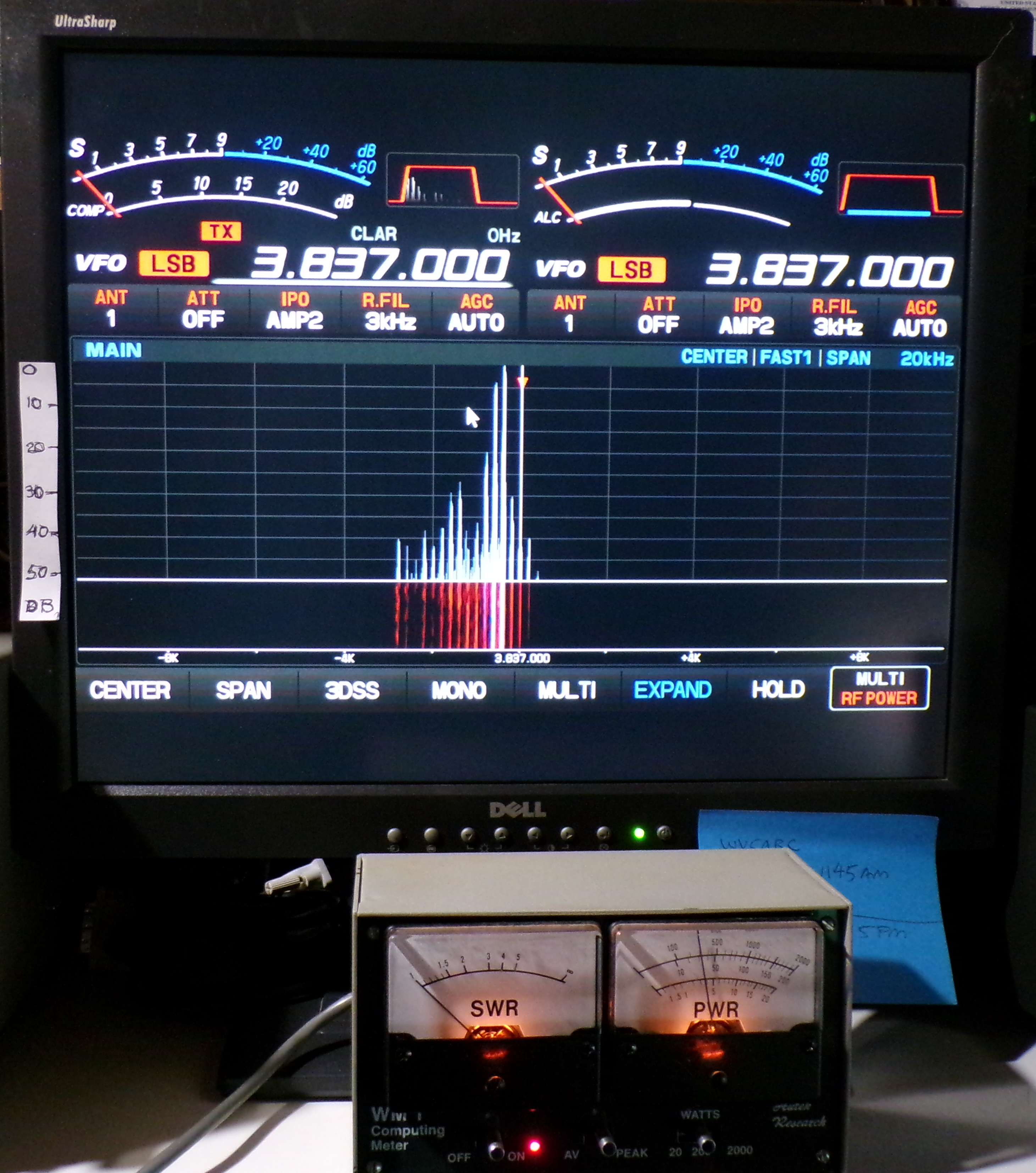
Here are screen shots of the large monitor I use to display the FTDX101D small radio display. Note the dual Autek computing wattmeter, which shows 40 watts output, typical of what is used to drive a linear amplifier. (It is annoying that it is necessary to provide an external peak reading wattmeter to be able to monitor that function. The FTDX101D can only display one parameter at a time, using the imitation "analog meter" display, when it could have used the same display space to monitor ALL functions simultaneously using bar graphs with an optional peak hold function.) These display photos show the very best possible performance obtainable using the settings enumerated at the end of this article. Those settings are for ZERO deflection of the ALC meter, 10 dB of the COMP meter (COMP=100), and 10 dB deflection of the AMC meter (AMC=35), and mike gain of 20 or enough to result in the above conditions. EQ is ON, and COMPressor is ON. Using COMPression results in better IMD performance. Power for the photos is set to 40 watts PEP. The best IMD performance is on the order of -30 to -35 dB for a steady state voiced vowel. Note that the left photo (E) the IMD products apppear more than 4 KHz below (left of) the supressed carrier, and smaller spurs appear in the area to the right of the suppressed carrier, in the UPPER side band. Total span for both photo is 20 KHz, or 10 KHz on either side of the carrier. Click on a photo to enlarge it.
 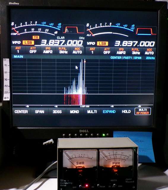
The photo on the left is steadily voicing "E", which results in more IMD products.
The photo on the right is steadily voicing "O" which is more of a sine wave audio signal and results in comparatively less IMD than "E."
Now that you know how to use this function and calibrate it, I invite you to play with your AMC, MIKE gain, and COMPressor settings to evaluate the effects of changes.
UPDATED 1/24/24 This discussion is not about digital modes, although it is relevant if you use a digital mode interface which enters the FTDX101 via the mike jack. TheFTDX101 has an internal USB sound card which is quite capable and I see no reason to use an external interface. That said, some attention to these settings and keeping the ALC meter at ZERO during ANY mode such as SSB or FT8 on the FTDX101 will result in fewer unwanted products in the transmitter spectrum.
Make sure to use "split mode" and "fake it" to minimize harmonic distortion when using digital modes with the FTDX101. Also, experiment in the proportioning of signal levels in the digital interface. Use the techniques recommended to observe distortion in voice modes presented here to evaluate your settings when using digital modes like FT8, for a clean signal. There is a rear panel jack for RTTY for an external modem which employs true FSK; it is the definitive method for a clean RTTY signal, and skips all the problems of using an audio modulation method (AFSK). I have not yet successfully set up RTTY using the internal USB connection.
Apparently serious issues exist with the internal sound card in the FTDX10, according to the link shown below. Some have given information on setting the level in the menus to a higher value so that the sound card does not run so high that it generates harmonics and distortion. Some have even taken to using an external digi sound card interface to clean up the distortion. People are seeing harmonic distortion of a single tone (tune mode), which suggests there is significant intermodulation distortion (IMD) as well in the FTDX10. This would lead you to believe that the source of the SSB distortion may lie outside the initial audio preamp stages and resides in the transmitter RF or ALC sections. In any event, I would strongly advise FT8 users owning FTDX101, FTDX10, FT710 or any other Yaesu gear employing AMC make certain absolutely no deflection on the ALC meter. Any deflection of ALC results in unacceptable distortion in the RF output. Whether there is anything that can be done to mitigate problems at lower levels remains to be determined by experiment.
https://groups.io/g/ftdx-10/topic/ft8_audio_harmonics/82436261
I have done extensive tests on my FTDX101D and was unable to duplicate the problems shown in the link below relating to the FTDX10. I deliberately selected a transmit spot in the lower 300 Hz region, turned "fake it" off, and even allowed some ALC meter motion. The built in spectrum display did not show significant distortion, under any condition I could devise. That's the good news for FTDX101D users. Here are my settings to get good control from the FT8 computer control screen. This seems to get audio drive for receive in a reasonable range, while also making transmit settings from the FT8 control panel in the computer not so touchy. Remember do not exceed 30 watts on any 100 watt radio to prevent over heating the final ammplifier. This is a continuous duty cycle mode like RTTY or AM.
FTDX101D SETTINGS FOR FT8 USING A USB CONNECTION TO THE INTERNAL SOUND CARD
- SELECT DATA-U AND THEN PRESS PRESET
- ADJUST RECEIVE BANDWIDTH TO 3 KHz IF NECESSARY
- AMC = 60
- POWER = 30 WATTS
- RPORT GAIN = 5
- DATA OUT LVL = 50
- TX BANDWIDTH = 100-2900
Since the AMC is always on, you must get that setting correct before setting the the mike gain level or COMPression.
Here is an experiment to learn what is going on with the AMC control, with a power setting of 20 watts. Set the displays to show COMP (really AMC because the compression is off) on the left and ALC on the right. Set the AMC level to 100 (as close to OFF as you can get.) Push the mike gain knob to switch off the processing. Slowly advance the MIC LEVEL starting at zero, while you watch the spectral display and ALC meter. At MIC GAIN = 0, you get no power output as observed on the external power meter.
Transmit a constant "aaaahhh" while advancing the MIC GAIN. First you will see the external power meter increase to about 8 watts average at a setting of 10 for MIC gain. No ALC action yet. The spectrum is tightly contained to the 3 KHz area to the left of the carrier marker.
Increasing above MIC gain of 10, note that ALC begins to rise, along with side products; focus on the area to the right of the carrier marker and notice the growth of distortion products. At MIC gain 13, the ALC quickly rises to the maximum suggested level or S9+5 dB. The distortion products also rapidly appear to the right of the carrier marker. They should be just below -35 dB or 4 lines up from the bottom. When stopping and starting the "aaaahhh" you will notice that the ALC meter kicks up to S9+20 dB and quickly falls to the normal range; the left COMP meter indicates AMC and also kicks up and falls to zero. This is a clear demonstration that the AMC and ALC circuits attack time is too slow to control overshoots which produce splatter. This happens even though the AMC is set to 100 or OFF. We have just proven that AMC cannot be defeated; possibly there is circuitry that couples some of the ALC signal into the AMC in an attempt to control the splatter resulting from slow attack time. The average reading power meter on the FTDX101D is about 5 watts for a 20 watt setting.
Advancing the MIC gain to 50 results in ALC reaching S9+30.
ZL3DW claims that even with the ALC driven well beyond its "normal" range, the distortion productes are still below -35 dB on a steady state signal such as a standard two tone test. This is stated on page 17 of the ZL3DW book. This is widely considered acceptable performance. This would not have been possible without the AMC feature. Those statements apply only to steady state inputs from the mike input.
Now stop any voicing and begin speaking normally, with words beginning with p, t, b, d, g, k. "Peter Piper picked a peck of pickled peppers." At a MIC gain of 50 and an AMC of 100, the left COMP meter (really AMC) will go full scale, over 20 dB of attempted compression, but the ALC meter will only peak just above the "normal" range. Observe that the spectral display shows products at about -40 dB spreading to ±8 KHz. While these are still below -30 dB, imagine passing that through an amplifier which has boosted your signal to a received strength of S9+40 dB. Your side products on "plosives" are S9 dB or more on side channels. An audio system with a fast attack time could have controlled this better. So we have to find a work around, to reduce complaints from neighboring channels.
The buckshot on adjacent channels will happen after a pause in speech and a restart, particularly with a speech "plosive" (p, t, k, b, d, g). A fast attack time will help suppress the overshoot resulting from these transients. A slow attack time will allow those transients to clip in the amplifier and result in splatter.
This reveals a fatal flaw in the testing procedures employed in transceiver distortion tests. They are all done using a two tone steady state signal, which allows the ALC, AMC, processing and other circuits to settle back from the uncontrolled peak of the initial audio containing a "plosive." Manufacturers and the ARRL test labs need to devise a test which checks for this very common and ignored transient response problem. It would prevent splatter and amplifier damage. This should be an essential component of the ARRL's "clean signal initiative."
My 1980 vintage Ten Tec Corsair looks great on a remote SDR with a spectral display through the exact same amplifier. But its transmit signal goes through an 8 pole crystal filter on the way to the final amplifer, and the internal ALC is extremely fast attack, with no overshoot. The FTDX101D transmit path is all SDR, no crystal filter on transmit path. Once again, modern SDR technology has to play "catch up" to thorough old school design.
ADJUSTMENT PROCEDURE WITH AMC ONLY: For a maximum punch signal, set the AMC to 100. Increase MIC gain to get an ALC deflection above the "normal" range, S9+20. Adjust AMC level down from 100 to get ALC near S7 with a steady state "aaaahhh" and note that average power has dropped about 10% from 11 watts to 10 watts. The scope shows little change in PEAK power or PEP. It does show reduction in flat topping without substantial loss of average power in the lower peaks. The COMP meter (really AMC) should stay at or below 10 dB for stead state, kicking into 20 dB at "five." My tests show -35 dB or better on the unwanted sideband products. This is with PROC LEVEL set to COMP and AMC RELEASE TIME set to FAST. This adjustment is stable for SSB with the processor OFF. I found a maximum setting of AMC of 55 was the end result. (This is NOT suitable for AM, more later.)
To experiment with better spectral purity at the expense of power output, change the setting of the AMC from 55 to lower numbers and watch the spectral display and ALC. At a setting of AMC=40, the ALC meter stops moving, the distortion products are below -40, and the RF power drops from average of 12 watts to 7 watts (60%). Of course, an amplifier can make up that loss.
BOTTOM LINE: The correct AMC setting lies somewhere between 55 and 40. With a setting of AMC=60, the ALC rides around the middle of its range or S5. This approaches the best compromise between adequate transmitter output and reasonable distortion control. For absolute best spectral purity, keep mic gain and AMC at levels that result in NO ALC deflection at all. Try to use the faster acting PROC level to regain as much of the punch as you can. This also seems to agree with the quoted Yaesu maximum recommended value of AMC=55 in various internet forums. My MIC gain was set to 20 with the XM-8500 mike.
There is little information on AM operation with the FTDX101. QST and other reviewers rarely mention AM performance. Here is a FTDX101 review from a hard core AMer. You may find the FTDX101 serves your purpose for casual AM operation. I personally do not know of any current "knob" transceiver which I would use for my primary AM station. I think such a thing is a mytical creature, like a Unicorn. But the Yaesu FTDX101 is capable of delivering a reasonable signal comparable to other available rigs. I also have a K7DYY Super Senior, a Viking II, and a DX-60 paired with an ICOM R8600, HQ-180, and an SB-303. Some of the SDRs currently available seem to put out good AM signals and have receivers good enough for daily use. The FTDX101 is designed for a purpose; AM is incidental, like all its contemporaries.
AMC definitely gets in the way of AM. Turn AMC=100. Watch the scope for 100% modulation and increase the MIC gain to get a proper amount of audio, higher than the 20-25 for SSB. A spectral display of the spoken letter "A" or like the Fonz used to say it, will show a well contained 6 KHz wide AM signal with acceptable distortion products. I would be very comfortable operating on 7295 on AM with this signal. ALC will kick up to S9+25 but ride around S9+10 dB with no modulation. AMC action as observed on the COMP meter should almost never move the needle. The POWER output will drop from 25 watts to as low as 12-15 watts on the POWER meter in the FTDX101 during modulation. An external true PEP reading power meter may not attain the normal theoretical four times the carrier level power indication, unless properly adjusted. My Autek WM-1 does show almost 4X power on peaks on speech modulation. The scope photos below show that the FTDX101 will attain 100% modulation on a steady tone or speech. Hammering the AMC circuit with more mike gain drive will only cause more carrier reduction, and may result in distortion, because the modulation can exceed 100% negative peaks. This type of modulation is the exact opposite of that employed in the DX-60 peak carrier control, where the carrier rests at a lower level, and jumps up during modulation, to reduce heating in the final or a subsequent amplifier. This effect is common in modern multimode HF transceivers.
These settings hold at any power level settings. I recommend an AMC setting of 100 for AM on the FTDX101 for fullest possible modulation. Its a fool's errand to attempt to use this obscure AMC circuit as a compressor on AM. If it were possible to connect an external audio processing chain, you would get much better results. I was unable to activate the rear audio input for AM or SSB mode from an external audio chain. I am still working on a possible connection of an external audio chain. If you are able to devise a solution to this problem, please let me know your solution.
If you drive excess audio on AM, the carrier reduces and harmonic distortion products appear at roughly 8 KHz from the carrier as observed on the FTDX101 spectrum scope (when correctly set to display transmit spectrum.) The ALC will also reduce the carrier on modulation peaks if you over drive the audio.
I have not experimented with using a negative DC voltage applied to the FTDX101D ALC input. Be certain that you do not exceed the maximum voltage specified in the Yaesu manual of -4 volts. Do not apply positive voltage. Damage can occur if you ignore these rules. Some other radios respond well to this measure to improve AM operation of a solid state transceiver. Some people use a high value series resistor in series with the feed to ALC, to reduce the current available; this possibly protects against transceiver damage by limiting current flow.
It is important that you experiment with the phasing of the wires from your mike for AM. Use the connection which produces maximum UPWARD peaks; all voices and mikes are different, and require adjustment, even when changing EQ settings. You can do this by inserting a short XLR extender cable. You can experiment with phasing connections by reversing pins 2 and 3 on one end. This way, you do not have to modify the HEIL cable or open the mike up to swap phase wires.
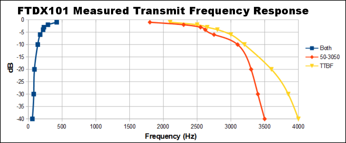
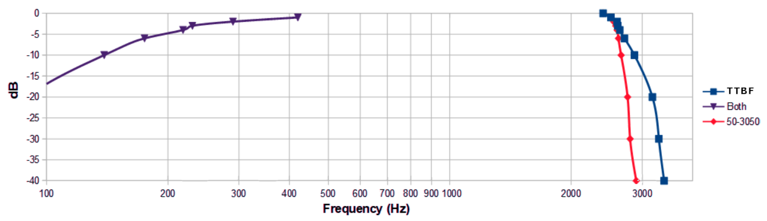
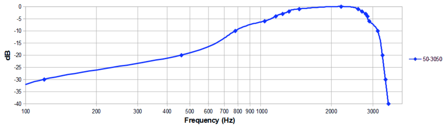
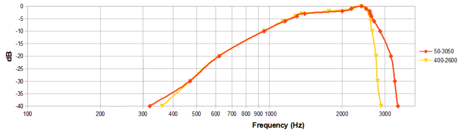
Since the compressor cannot be activated for AM mode, you will be using the EQ settings for PRMTRC, not P PRMTRC. If you wish to use compression or processing on AM, you will have to provide external equipment for that purpose. Adjust those "PRMTRC" EQ settings accordingly for best AM and SSB ragchew sound, and use the "P PRMTRC" EQ settings for a more aggressive sound for poor SSB conditions or contesting. For AM, you want a TX BW of 50-3050 or TTBF. I did not find any useful improvement using TTBF, and abandoned it. See the measured frequency response curves in the final section. Cliff's Notes: TTBF doesn't work; don't use it. The receive band width is controlled by pressing the upper mode selection button and holding it til a menu pops up on screen. Select either AM or AM-N for narrower receive. This has no effect on transmit band width. The width knob on the right hand of the radio has no effect. There is no reason in an SDR that this could not be implemented in a future software update.
The FT-450D has three AM receive band width settings. The new FT710 even has an EQ for RECEIVE audio! I would love to see a receive EQ included in the next round of software updates for the FTdx101. You can use the CONTOUR control for that also, but then it cannot be used for other useful QRM reduction. I have a Visaton speaker installed in a thrift store speaker box which brightens up the high end nicely. Bass response with this system probably will not satisfy hi fi AM aficianodos, but it works well on SSB and CW. See my other article on FTDX101 receive audio and speakers for parts sources and ideas.
I did some audio sweeps of the transmit speech amplifier. They are shown below.
I have done no experiments with FM mode on the FTDX101. I can only speculate that the circuitry and response time for that mode are similar. However, in FM the power level remains relatively constant for voice modulation. The EQ settings may be comparable to those used for AM. If you use a remote SDR to check your FM sound and band width, be sure to use NARROW FM settings in the menu and keep tests very brief at time when the band is not busy. Do not use FM at 100 watts output; it is a continuous mode like RTTY, and power should be reduced to 30 watts or less to prevent overheating the finals. I would be interested in hearing from anyone who has played with the transmit audio and equalization for FM on the FTDX101.
The compression level cannot be properly set until the AMC is set. We begin with MIC gain of 20 - 23 and AMC set to 40-55, as previously determined for SSB. The key is the initial default setting of AMC=40-55, which Yaesu does not give you in its procedures. The processor cannot be used on AM, its disabled. This is an audio processor, not an RF processor.
Press the MIC gain control to cause the PROC light to the left of the mic gain knob to come on, and turn on the Processor. (Note that the feature to use CW while in SSB mode automatically assigns this knob to CW SPEED. Change this menu item if you need to, or you will not be able to perform audio adjustments in voice modes.) The PROC knob now adjusts only the PROC, not the AMC as before. See page 51 of the Yaesu manual, and the software update sheet (which can be downloaded from Yaesu.com.) The LED to the right of the mic gain knob indicates whether the key jack is set to a straight key or an electronic keyer.
Before setting the COMPressor level, set the AMC to 40 for lower distortion or up to 55 for more output. ZERO ALC readings are directly correlated with lower distortion products and splatter. The better controlled ALC action seems to suggest that using compression all the time on SSB might improve your signal purity. This suggests the compressor attack time is faster and controls "plosives" or transients in speech better. Listen to your signal on a remote SDR and/or record it and play it back, to get an idea of what you prefer for processor and EQ settings for transmit audio. The internal Yaesu MONITOR function may or may not be definitive due to whether your mike and headphones are properly in phase with the bone conduction in your head.
The correct setting for COMPression seems to be 100, and you have to increase the MIKE GAIN to adjust the drive higher to get a COMP meter reading of around 10 dB. Otherwise, you will get no deflection of the COMP meter. The distortion products experiments with these audio tests are encouraging. Remember an amplifier is likely to add distortion on the order of -30 dB. It will make you louder but also increase the strength of your exciter distortion products, if you don't get these settings right.
The majority of transceiver manufacturers display their transmit equalizers in a simple graphic EQ sliders or bass and treble format. Yaesu does it differently, but there is a way to display the effect of the parametric EQ controls in a comprehensible format. In the OPERATION SETTINGS/TX AUDIO menu, there are non intuitive parametric EQ settings which are not easily understood by the average operator. The Yaesu audio EQ is the work of Bob Heil, the noted amateur audio expert and microphone manufacturer. The EQ settings can also result in overload and splatter if misadjusted.
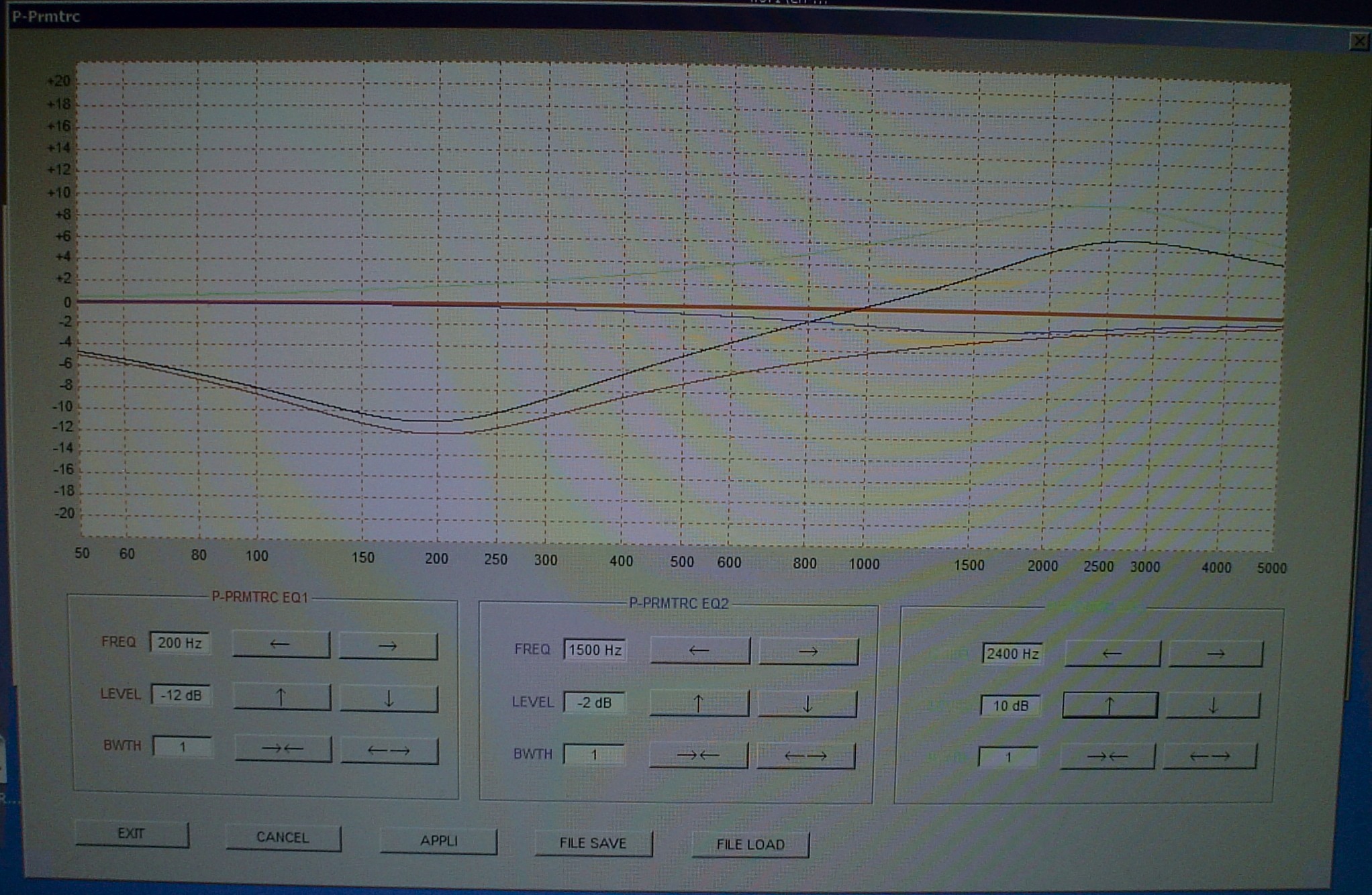 In addition to this, we are confounded by the Parametric EQ settings. These are not intuitive. I owned a Yaesu FT-950 which had the same Bob Heil designed system. At that time, Yaesu furnished a very helpful utility to control the FT-950. You do not need to have a FT-950 to profit from the EQ setting utility. Here is what it displays when you adjust Q and levels and frequencies in a parametric EQ, which is equally applicable to the FTDX101D. It shows you the effect of EACH EQ section, and the final composite result. In addition to this, we are confounded by the Parametric EQ settings. These are not intuitive. I owned a Yaesu FT-950 which had the same Bob Heil designed system. At that time, Yaesu furnished a very helpful utility to control the FT-950. You do not need to have a FT-950 to profit from the EQ setting utility. Here is what it displays when you adjust Q and levels and frequencies in a parametric EQ, which is equally applicable to the FTDX101D. It shows you the effect of EACH EQ section, and the final composite result.
This software utility assumes that the other elements in the FTDX101 are flat frequency response. That may not be the case. One ham used an audio noise generator injected into the mike input and a spectrum analyzer connected to the RF output to measure how much EQ was needed to actually obtain a flat frequency response over the 50-3050 Hz spectrum. His findings were astonishing to me. I had wondered why the unexpected amounts of low cut and high boost in my final EQ settings were necessary. Watch his youtube video and take note of what his Q and dB levels are. He is using -10 dB cut for lows and 4 dB boost for highs to get a flat response! I plan to try to verify this finding using simpler equipement, a sine wave generator injected into the mike input and a power meter, to do a sweep of the audio response of the speech amplifier. Another ham has done a SPICE analysis of that circuitry, and it shows some other surprising findings. They are discussed near the end of this article in the TTBF section.
https://www.youtube.com/watch?v=_-FT_y8zpe8
For a full discussion of the use of this program see
my Yaesu PCC-950 Software Review.
Download the PCC-950 utility program from the Yaesu web site at:
https://www.yaesu.com/downloadFile.cfm?FileID=6739&FileCatID=42&FileName=PCC-950_V124.zip&FileContentType=application/x-zip-compressed.
The EQ display at the right is the one I used on my FT-950. Its a pretty mild amount of EQ, because it does not have all the complications of the FTDX101 peaky audio stage in the speech amp.
| It is really not necesssary to get overly upset about the parametric EQ if you think differently about it. If you keep the settings of Q or BWTH (bandwidth) to less than 2, you can easily think of the Yaesu EQ as a standard 3 band EQ: LOW, MID, HIGH. Besides the dB boost or cut, you also get to choose the center frequencies of the LOW, MID, and HIGH EQ bands. Once you adjust BWTH to 3 or more, it gets peaky and hard to visualize, unless you use the Yaesu utility I cited. Does that make it a little easier to visualize? |
|---|
My EQ settings are summarized in a table at the end of this article.
I had thought I could work around the problems associated with the low level speech amplifier by connecting an audio system to the rear jack normally used for RTTY. This would bypass all the elements associated with the front panel mike input. All the external audio equipment would be easily understood, fully documented, and have a fast enough attack time to be effective in suppressing splatter and increasing talk power. I did this before with my FT-950.
I bought a W2IHY cable for the rear connector and tried it; it was wired correctly per the instruction manual for the FTDX101D and ohm meter checks. The rig did not respond to single ended line level audio at the rear connector, despite my attempts at finding a menu setting. One internet source states that you have to activate the PTT via the rear connector also, otherwise the rear connector audio will not be employed. There was no information from W2IHY on this problem, if used with his processor equipment. I hope a future software update corrects this situation. The menu does not seem to actually choose the input. This is frustrating, because I had good Behringer audio gear I had successfully used with my FT-950, as well as a newly acquired MAX processor (which worked great on my AM gear, a K7DYY transmitter.) I was unable to get this to work correctly without distortion when using the mike jack; I am still working on this, hoping an isolation transformer will cure the problem. If you have success, please let me know.
https://www.internetwork.com/MAX/
I have heard that the rear RTTY input can be used on voice modes IF YOU ACTIVATE THE PTT FROM THAT JACK. I have not tried this. The W2IHY cable does not have a PTT connection. I don't know if the W2IHY system works without the PTT being activated from the rear connector.
Another point you should be aware of is that the front panel mike input is active when using the USB internal FTDX101D sound card rear input for digital modes. This is true regardless of menu setting. I even asked Yaesu about it, and they confirmed it. So when you operate FT8, be sure to disconnect the mike or turn the mike gain down to zero to avoid shack noise from going out over the air when operating FT8. Also turn off the "Windows sounds" on your computer to prevent noises from the computer being transmitted. On FT8, you regularly hear "new country" or "youve got mail" from improperly configured FT8 or windows software.
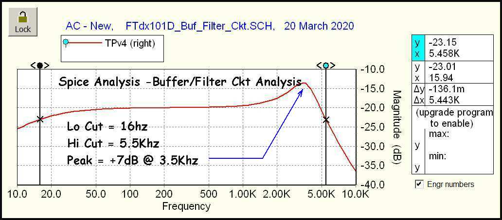 I have found that TTBF does not actually increase the band width to 4 KHz because of the response of the audio preamp and filtering. There is also a very peaky audio filter (+7 dB) that might contribute to circuit overload and consequent splatter I observed when using the kind of high frequency boost I employ in the EQ. I observed a bright area in the remote SDR waterfall at around 3.5 KHz from the carrier frequency which made me uncomfortable. I enjoy the radio and the good reports I get with the 50-3050 setting; this choice disappears when TTBF is added. You may choose to experiment further with TTBF; if you find a solution you are confident about, please write me. I have found that TTBF does not actually increase the band width to 4 KHz because of the response of the audio preamp and filtering. There is also a very peaky audio filter (+7 dB) that might contribute to circuit overload and consequent splatter I observed when using the kind of high frequency boost I employ in the EQ. I observed a bright area in the remote SDR waterfall at around 3.5 KHz from the carrier frequency which made me uncomfortable. I enjoy the radio and the good reports I get with the 50-3050 setting; this choice disappears when TTBF is added. You may choose to experiment further with TTBF; if you find a solution you are confident about, please write me.
For more information, see the K6JRF website, which is very informative about TTBF and FTDX101 audio. He is an ESSB advocate. I include this graphic as encouragement for you to explore that web site for a fuller discussion. It is well worth your while if you want to try out TTBF and ESSB with the FTDX101 or FTDX10.
https://www.k6jrf.com/FTdx101_ttbf_Analysis.html
For balance, I offer a different take from W8JI. This is the ham who designed the most popular amplifiers used today, and the antenna analyzers many of us have. He explains how distortion products are generated. He explains why a wide audio spectrum in a transmitter, especially with boosting the bass and treble ends of the spectrum is more prone to generating a wide signal. He explains a 6 db discrepancy in test methods for transmitters. He explains why a three tone test is needed to accurately portray transmitter distortion. Its required reading if you want to understand the FTDX101 distortion products and how to minimize them.
https://www.w8ji.com/transmitter_splatter.htm
 On the web, you will find a youtube video that shows someone using a broadband noise generator and looking at the spectral display. He then adjusts the Yaesu FTDX101 EQ settings to get a flat response. My results differ; they are done with simpler brute force methods, using an audio generator and power meter. There is no substitute for actual measurements rather then speculation with a SPICE analysis of a single audio stage. This constitutes a complete end to end test of the entire transmitter system from mike input to antenna output. I used an HP 204 sine wave generator to feed the FTDX101 input. I set AMC=100. EQ was set to OFF. I observed POWER out and ALC on the FTDX101 display. Power readings were converted to dB on a calculator. No ALC action was allowed, so that any gain compression was not a factor in the measurements. These measurements were taken in SSB mode at 100 watts into a Bird Dummy Load with 1.000:1 SWR. Reference zero dB was at 1 KHz. Low end roll off was sooner than anticipated. TTBF high frequency performance offered little improvement over standard 50-3050 TX Bandwidth setting. At higher frequencies, the reduced filtering of possible distortion products in TTBF mode outweighs any minimal advantages. Overload in the region of the SPICE analysis peak region are possible in TTBF mode. My earlier conclusion to avoid TTBF was confirmed for both AM and SSB. I get good reports with 50-3050. But try it for yourself; you may think otherwise. On the web, you will find a youtube video that shows someone using a broadband noise generator and looking at the spectral display. He then adjusts the Yaesu FTDX101 EQ settings to get a flat response. My results differ; they are done with simpler brute force methods, using an audio generator and power meter. There is no substitute for actual measurements rather then speculation with a SPICE analysis of a single audio stage. This constitutes a complete end to end test of the entire transmitter system from mike input to antenna output. I used an HP 204 sine wave generator to feed the FTDX101 input. I set AMC=100. EQ was set to OFF. I observed POWER out and ALC on the FTDX101 display. Power readings were converted to dB on a calculator. No ALC action was allowed, so that any gain compression was not a factor in the measurements. These measurements were taken in SSB mode at 100 watts into a Bird Dummy Load with 1.000:1 SWR. Reference zero dB was at 1 KHz. Low end roll off was sooner than anticipated. TTBF high frequency performance offered little improvement over standard 50-3050 TX Bandwidth setting. At higher frequencies, the reduced filtering of possible distortion products in TTBF mode outweighs any minimal advantages. Overload in the region of the SPICE analysis peak region are possible in TTBF mode. My earlier conclusion to avoid TTBF was confirmed for both AM and SSB. I get good reports with 50-3050. But try it for yourself; you may think otherwise.
These settings may extrapolate to the FTDX101MP, FTDX10, and possibly the FT710.
| The simple take away from this discussion is that the GOAL of all this is to totally eliminate any movement of the
ALC meter to stop splatter and IMD products from making your signal excessively wide. The AMC settings around 40 favor this outcome. PEAK power will still
be 100 watts or whatever you set with power level. Settings near 55 will increase AVERAGE power as indicated on the FTDX101 power meter, which is average
reading, not peak reading. If you are driving an amplifier, it is better to feed it a clean signal by using settings of AMC near 40, and let the amplifier make
up for any power loss caused by conservative AMC settings. The COMPRESSOR rather than the AMC makes for dense punchy signal as shown
in the recommended settings at the bottom of the table. The EQ settings work for my XM-8500 mike, my voice, and my operating habits. You may find them useful as a starting point for your settings. |
|---|
| MENU OR KNOB | SETTING ITEM | DEFAULT | CORRECT SETTING | COMMENT |
|---|
| OPERATION SETTING/TX AUDIO | PROC LEVL | AMC | COMP | ENABLES PROCESSOR ADJUSTMENT |
| OPERATION SETTING/TX AUDIO | AMC RELEASE TIME | MID | FAST | GOOD BUT DOES NOT HELP ATTACK TIME |
| RADIO SETTING/SSB | TX BPF SEL | 100-2900 | 50-3050 | BEST AUDIO FOR NORMAL |
|
| OPERATION SETTING/TX AUDIO | PRMTRC EQ1 FREQ | | 300 | ACTIVE DURING AMC MODE (RAGCHEW) |
| OPERATION SETTING/TX AUDIO | PRMTRC EQ1 LEVEL | | -6 | CUT LOWS |
| OPERATION SETTING/TX AUDIO | PRMTRC EQ1 BWTH | | 1 | LOWEST Q SETTING FOR SMOOTH CURVE |
| OPERATION SETTING/TX AUDIO | PRMTRC EQ2 FREQ | | OFF | NOT NEEDED |
| OPERATION SETTING/TX AUDIO | PRMTRC EQ2 LEVEL | | -3 | |
| OPERATION SETTING/TX AUDIO | PRMTRC EQ2 BWTH | | 1 | |
| OPERATION SETTING/TX AUDIO | PRMTRC EQ3 FREQ | | 2400 | |
| OPERATION SETTING/TX AUDIO | PRMTRC EQ3 LEVEL | | 10 | MAX BOOST FOR PRESENCE RISE |
| OPERATION SETTING/TX AUDIO | PRMTRC EQ3 BWTH | | 1 | LOWEST Q SETTING FOR SMOOTH CURVE |
|
| OPERATION SETTING/TX AUDIO | P PRMTRC EQ1 FREQ | | 300 | ACTIVE DURING PROC MODE MAX DX PUNCH |
| OPERATION SETTING/TX AUDIO | P PRMTRC EQ1 LEVEL | | -13 | CUT LOWS |
| OPERATION SETTING/TX AUDIO | P PRMTRC EQ1 BWTH | | 2 | |
| OPERATION SETTING/TX AUDIO | P PRMTRC EQ2 FREQ | | 1500 | |
| OPERATION SETTING/TX AUDIO | P PRMTRC EQ2 LEVEL | | 6 | BOOST MIDRANGE |
| OPERATION SETTING/TX AUDIO | P PRMTRC EQ2 BWTH | | 1 | |
| OPERATION SETTING/TX AUDIO | P PRMTRC EQ3 FREQ | | 2500 | |
| OPERATION SETTING/TX AUDIO | P PRMTRC EQ3 LEVEL | | 6 | BOOST HIGHS |
| OPERATION SETTING/TX AUDIO | P PRMTRC EQ3 BWTH | | 3 | QUICKER DROP OFF FOR LESS SPLATTER |
SSB MODE KNOB SETTINGS |
| MIC GAIN AMC MODE | | 20 | 20-25 | PROC OFF |
| AMC | | 45 | 40-55 | SSB MODE
40=less distortion, 55=max power |
SSB PROCESSOR ON MODE KNOB SETTINGS |
| MIC GAIN PROC MODE | | 30 | 20-50 | PROC ON, more drive needed |
| AMC PROC MODE | | 45 | 40 | for min distortion |
| PROC | | 80 | 100 | increase average power output & density |
AM MODE KNOB SETTINGS |
| MIC GAIN AM MODE | | | 20-50 | COMPRESSION DISABLED IN SOFTWARE
adjust for 100% modulation on scope |
| AMC | | | 100 | SET AMC TO 100 TO DISABLE IT
lower settings will not allow 100% modulation |
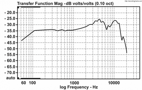
The frequency response curves below are for the FTDX101 in SSB mode under various EQ conditions. In this case, audio from the HP 204 generator is applied via a 20 dB attenuator to the unbalanced input of the FTDX101. The transmit bandwidth is adjusted as stated. In all cases, no ALC, AMC, or COMP action is allowed, by adjusting mike gain drive appropriately. The amount of EQ applied may seem extreme, -10 dB bass cut and +10db treble boost. I have confirmed my settings with another trusted friend with an FTDX10 and others on the air with similar EQ settings. However, the actual amount of EQ is moderated by the AMC, ALC, or COMPression applied AFTER the EQ. Any automatic gain reduction reduces amplitudes and tends to make amplitudes nearly the same for varying frequencies. In other words, compression AFTER the EQ undoes much of what the EQ did. You have to overdo EQ in order to correct for that. Post compression EQ also has down sides, but that is another technical discussion. How the COMPressor comes into play is another speculation. Back in the day, user manuals provided at least a block diagram of functions along with a rudimentary explanation of circuits. Yaesu omitted this, along with other basic information needed to attain acceptable SSB performance with a minimum of splatter.
 | NO EQ |
|---|
 | PRMTRC EQ |
|---|
 | P PRMTRC EQ |
|---|
I tried but abandoned efforts to use external audio gear, due to problems interacing it with the FTDX101. With my old FT-950, the DSP transmit audio compressor did not have fast enough attack time, and introduced grundge on the leading edge; there was no option but outboard solutions. In that case, I got it to work via the mike input. If you are able to get the FTDX101 to work with the rear RTTY input jack, I would like to hear from you.
This is basically an SDR with knobs. This opens up a lot of possibilities. For instance, rather than referring to this chart (which is posted at my operating position), why couldn't Yaesu offer "profiles" like some of the SDRs do? SSB 1 for ragchew, SSB 2 for "space shuttle audio" for contesting, AM for a more mellow sound. And why does the "afterthought" for FT8 require you to select either SSB or a digital mode, then click on "PRESET" to load the parameters for that mode? FT8 is the more popular than all other modes combined. Kludgey, but it works better than nothing at all. I am not being so fussy that they have to duplicate the smell of hot dust on vacuum tubes for me. But with software, you should be able to fix things up in an update better than this.
In my opinion, if you have to have a tower or desktop computer as large as the radio, and the radio has no knobs, you don't have a radio, you have a "PERIPHERAL."
In my opinion, if you need a pile of audio gear next to your transceiver as big as the transceiver, just to get acceptable transmit audio, you may need a new radio.
There is no way to sugar coat this. If you do not adjust the FTDX101 AMC for zero ALC meter deflection, you will have gawdawful splatter.
For Yaesu to not have issued a bulletin to alert users of this problem and how to deal with it by this late date is inexcusable.
OK, curmudgeon mode off. This transceiver has a great receiver, and I am willing to put up with the quirks of the transmitter to keep it around. Is the AMC a part of the ALC circuit with a different threshold setting? I might explore that. Yaesu does not have a block diagram or tell us "what's in the box." Remember when manuals used to have that information?
There is a pervasive problem right now in currently available amateur transceivers. Improper adjustment of an FTDX101D or FTDX101MP absolutely will result in nasty splatter and IMD products for an unnecessarily wide transmit signal. Had the ALC circuit been designed with a lower threshold, to begin limiting drive BEFORE the distortion began, this problem would have been less awful; better time constants should have been chosen as well. ANY ALC action will result in distortion. Make adjustments with the goal of ZERO ALC meter movement. Most all RF designs using FETs or LDMOS devices cannot seem to break the -30 dB IMD barrier. For instance, QST reviewed the fTDX101D and the FTDX101MP. No warning of potential splatter or IMD distortion in the transmitter was published. I did not take a carload of test equipment to the dealer when I evaluated this radio. Subsequently, problems surfaced beyond my control. I did due diligence in researching the AMC feature, which can go a long way in suppressing IMD on the transmit signal. As long as you keep AMC settings more toward 40-45 in SSB, the IMD products will be as low as the inherent Yaesu design permits, on the order of -30 dB. Adaptive predistortion is only offered on some esoteric SDR brands like Anan and FLEX. My KPA1500 has an output port for such a system, but the feature is not implemented in the matching K4 transceiver. None of the current big 3 transceiver manufacturers offer the predistortion feature to reduce IMD.
• https://ieeexplore.ieee.org/document/1411217
• https://westminsterresearch.westminster.ac.uk/item/92x3w/distortion-correction-of-ldmos-rf-power-amplifiers-using-digital-predistortion
• https://groups.io/g/FTDX-101D/topic/76800877
Pay special attention to the comments of K4TK/Tim.
• "Transmit distortion - For SSB, TX IMD performance has not really improved from the 1960's (actually worse)..granted most rigs are poorly used (a shame in itself) - but many TX output stages are adequate at best and some downright dreadful - this is not an insoluble technical problem with proper output stage and ALC design. Apache Labs have brought at least two SDR models that offer a software feedback feature to reduce the 3rd order IMD products on transmit to very low levels. All modern transceivers and linear amplifiers should have a 'pure signal' feedback option to bring super clean signals onto our bands..but they don't. I asked Rob Sherwood about the appalling state of some transmitted signals and why the big manufacturers have no software options for a pure signal capability. He indicated it may be down to the computing power or firmware design in the transceiver architecture."
- from G3ZPS http://www.g3zps.com/about.html
•My comment: Or just sloppy design due to software engineers who have limited RF experience.
For the time being, I will continue to operate this radio in as conservative a fashion as I can. But I am optimistic that newer radios will be even better in the future, especially on the transmit side. Unless someone can offer me a transceiver with equivalent receive performance which has improved lower IMD distortion products on transmit, I remain among the aficionados for the FTDX101. Other manufacturers have failed to produce anything that is significantly better on transmit IMD, other than FLEX and ANAN.
It is clear that I have reached the end of the possible adjustments which are limited by the speech amplifier and AMC circuits associated with the front panel mike jack of the FTDX101. It is also clear that in SSB and digital modes, the way to avoid distortion is to have ZERO movement of the ALC meter. Something other than the hand mike will go a long way to improving audio.
I hope you enjoy operating your Yaesu FTDX101 as much as I do.
My other articles about the FTDX101D
• FTDX-101D Review
• WSJT & FT8 Settings for FTDX101D & FTDX10
• N1MM Logger Settings for FTDX101D & FTDX10
• Replacement Upgrade Speaker for Yaesu FTDX101MP and SP-101
Don't let this happen to you.... 
|